
What is a Solar Rapid Shutdown System?
The rapid shutdown system is a required safety feature for most rooftop solar projects in the US today. It performs rapid shutdown, a PV equipment function to reduce shock hazards by reducing the output voltage and power of conductors when an initiation device signals it is necessary.
When it operates correctly, the rapid shutdown system protects firefighters by ensuring they are not exposed to high-voltage DC conductors while responding to structure fires. This is a major concern when firefighters must vent roofs with PV arrays.
The purpose of rapid shutdown is simple: minimize firefighters’ exposure to electrical hazards from PV system components. The field data is more complicated.
This article addresses key questions about rapid shutdown systems and the devices they contain:
- What is a rapid shutdown system?
- Why are solar rapid shutdown devices common in the US?
- Do solar rapid shutdown devices improve the safety of PV systems?
- Do US codes and standards ensure PV system safety and protect firefighters from energy hazards?
For readers asking how does solar rapid shutdown work, it reduces the voltage and power of PV conductors in a defined time period, or activation time. An inverter that disconnects from AC power, is turned off, or turns off due to an error (or fault) is a common way to initiate the rapid shutdown sequence in a rapid shutdown system.
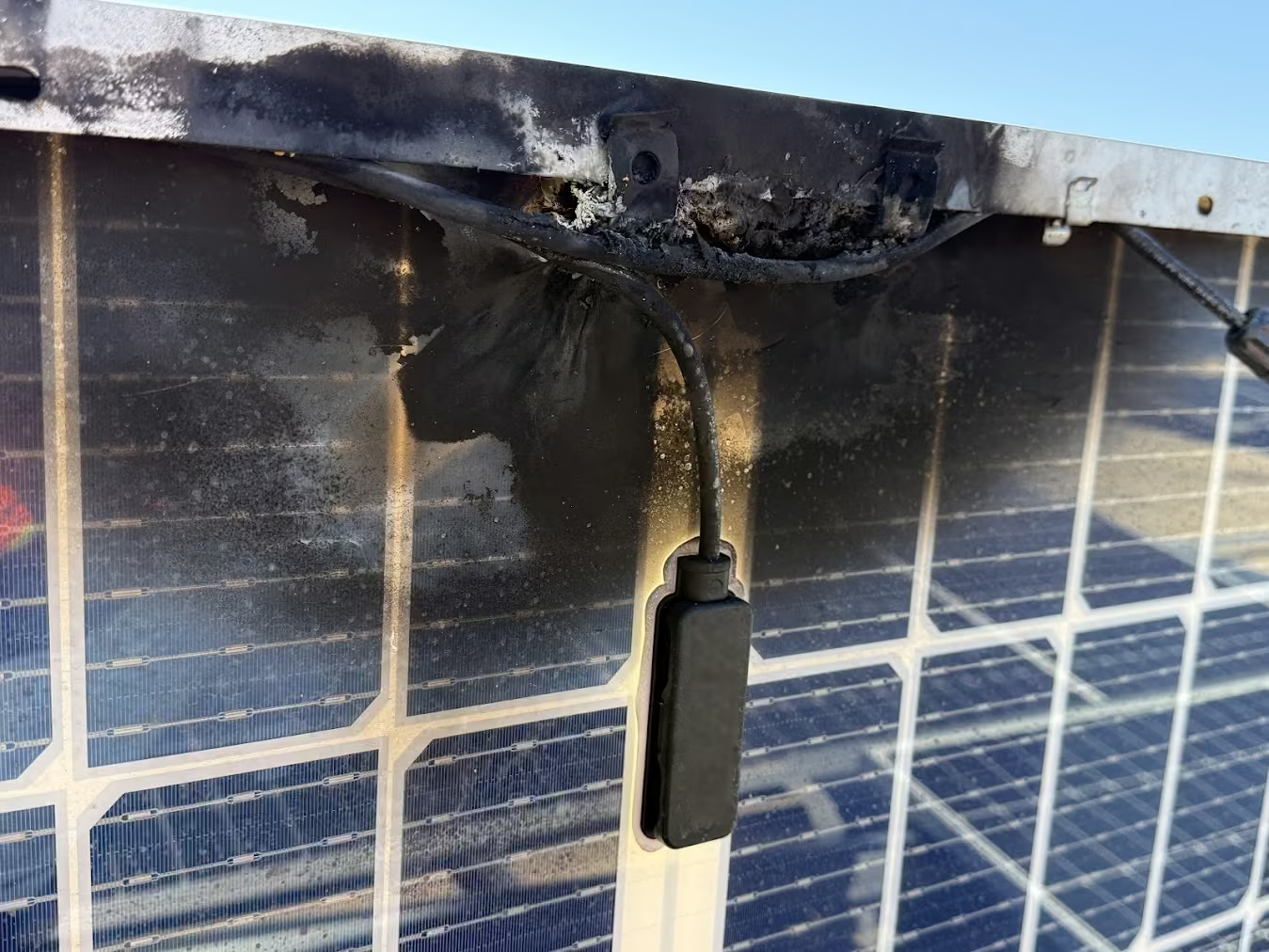
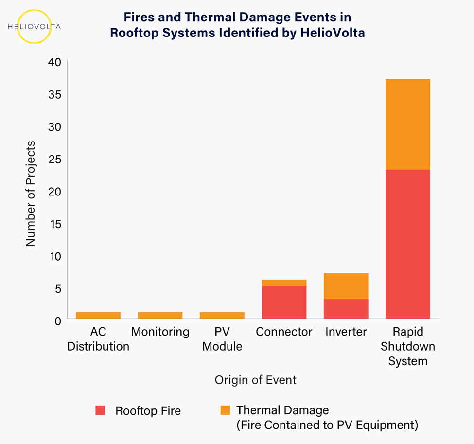
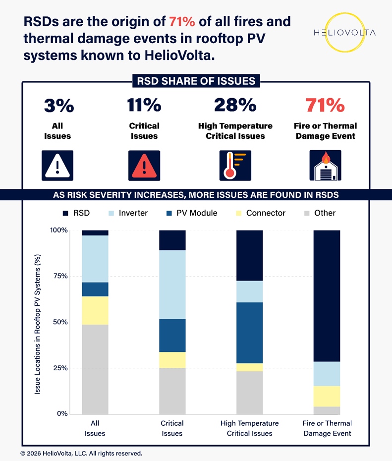
We’re addressing rapid shutdown because the HelioVolta team has recorded fires or thermal damage events (a fire contained to a specific component) at 52 different rooftop PV systems in the US to date, and, in 71% of these incidents (37 systems), rapid shutdown systems were the origin and the most likely root cause of the event.
In contrast, critical thermal issues are found most frequently in the DC distribution section of the ground-mounted PV systems and solar carports in HelioVolta’s broader dataset.
What is a Rapid Shutdown Device?
A solar rapid shutdown device is a safety component for solar systems that quickly reduces the voltage of PV components. Several different classes of equipment can provide this function, which is usually triggered manually by a switch or automatically by array- or module-level power electronics (MLPE).
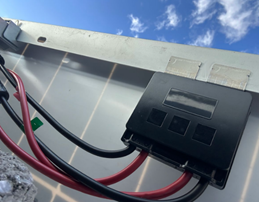
Solar rapid shutdown systems for commercial PV systems often use a specific component known as a module-level rapid shutdown device (RSDs), or solar RSD. We define RSDs as a class of module-level power electronics (MLPE) with a single purpose: reducing the voltage of PV conductors as required by the National Electrical Code (NEC) in the US. In other words, an RSD is a system component that only provides rapid shutdown and no other function. They are generally marketed as a cost-effective, NEC-compliant safety measure.
RSDs were rarely, if ever, deployed in the field when our careers began in the early 2000s and 2010s. The rapid commercialization of RSDs is the direct result of the evolving NEC, which first introduced rapid shutdown as a requirement for rooftop PV systems in 2014.
By 2019, RSDs, essentially a brand-new category of MLPE, were frequently installed for code compliance in US commercial solar applications. Based on HelioVolta’s experience with a range of RSD models made by five different manufacturers, we believe:
- Empirically, RSDs, as a product class, are prone to failure.
- When RSDs fail, they can overheat dangerously, increasing the frequency of high-risk reliability incidents, such as PV system fires, thermal events, and thermal device failures.
- RSD deployment should be replaced with more effective firefighter safety provisions that eliminate potential for electrical shocks from PV systems.
Other types of MLPE are microinverters and power optimizers, which differ as follows:
- Unlike RSDs, power optimizers and microinverters optimize module-level power output, reducing the impact of shading and mismatch.
- Power optimizers and microinverters were used in US rooftop systems before the implementation of rapid shutdown requirements and are common outside the US.
- Power optimizers usually have two-way communications with an inverter, offering an additional precision layer of telemetry.
Please note: microinverters are primarily used in residential systems and are not represented in HelioVolta's data set.
Solar RSD Safety: Initial Report and Industry Feedback
In March 2026, HelioVolta published a technical report, “Unintended Consequences: Rapid Shutdown Devices and Safety in Commercial Solar Systems” to highlight our team’s RSD safety concerns. At that time, we had documented 21 rooftop fires originating in RSDs.
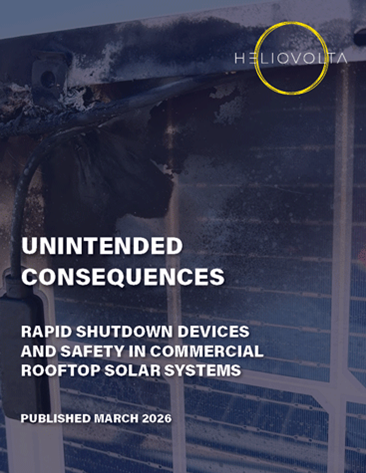
The report highlighted our increasing concerns that regulators, policymakers, and the broader solar industry were materially underinformed about the safety risks of RSDs: there is no national database for the root causes of PV system fires, much less RSD failures.1
While the problems associated with these devices had become an open secret among field professionals, many asset owners and system hosts remained in the dark. (Host companies have PV systems owned by third parties installed on their facilities.)
By sharing HelioVolta’s RSD field data and research, we hoped to spur more transparent public discussion of RSD failure risks. The publication was used by several advocates for revisions to the NEC’s rapid shutdown requirements, including our CEO, David Penalva. His formal public input to the next NEC revision is discussed in more detail below.
Solar professionals, asset owners, first responders, RSD manufacturers, and other stakeholders began contacting us soon after our report’s publication. Almost immediately, we received reports of two more rooftop fires caused by RSDs and a third rooftop fire caused by an array-level RSD.
We also learned that RSDs have been deployed outside the U.S. proactively as a best practice. Solar professionals in other markets have assumed that rapid shutdown systems improve project safety simply because they are required by our country’s NEC. As a global thought leader for renewable deployment, the US is misguiding global markets.
Ongoing discussions with first responders have also demonstrated the vital importance of protecting firefighters from electrical hazards in PV systems and the deficiencies of current safety measures. Firefighter safety should be prioritized by solar developers, installers, and operations and maintenance providers. Any changes to the NEC must improve the safety measures in place for firefighters, not roll them back.
Unfortunately, we also learned that a recent fire at a solar-powered home in the Southeast US injured two first responders, one of whom suffered an electric shock from a PV component. Though the cause of the incident itself is unclear, the rapid shutdown function did not guarantee firefighter safety. We must continue pursuing more effective ways of protecting first responders. (Please note: HelioVolta was not involved in this event in any capacity and we have not seen official reports pertaining to the incident.)
RSD Failures: The Products are the Problem
We acknowledge valid feedback that HelioVolta’s recent RSDs report overemphasized the impact of workmanship errors on RSD failures. Some readers incorrectly concluded that contractors are wholly responsible for RSD failures. We are correcting this misconception here.
Our first step was to conduct more granular analyses of HelioVolta’s failure root cause analysis inspections across all rooftop projects in our database, as well as data from other types of inspections. Charting the share of issues per component against issue severity (see figure below) definitively links RSDs to high-risk safety failures. When we tabulated failure events for our report, we focused on systems containing RSDs only.
Our analysis indicates that RSDs increase the risk of thermal events, even in correctly installed PV systems on commercial rooftops:
- While RSDs generate only 3% of all issues documented by HelioVolta in rooftop PV systems, 28% of high-temperature critical issues (e.g., hotspots, signs of overheating, thermal failure) are found in RSDs.
- RSDs are the origin of a staggering 71% for fires and thermal damage events known to HelioVolta.
In other words, RSDs are associated with more rooftop PV system fires than any other component that HelioVolta encounters in the field.
Across our broader dataset of utility-scale and commercial carport and ground-mount projects, HelioVolta has observed more critical thermal issues in connectors, electrical balance-of-system components, and PV modules than in RSDs.
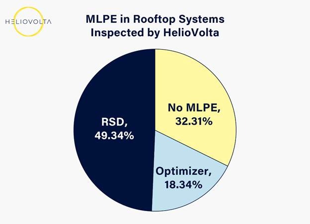
We acknowledge that these findings are based on a limited sample of >500 rooftop PV systems in the US, and that half of the rooftop systems inspected by HelioVolta contain RSDS (see graph below).
HelioVolta’s field data for rooftop systems comes from commercial system inspections and is not applicable to residential projects. More field data from a broader sample of projects is necessary to measure the true scale of RSD failures, so we encourage our industry peers to share their findings.
With this need for more robust RSD data and information in mind, the following sections of this article walk through essential facts about RSDs and provide more context for their safety risks.
How does an RSD work?
When the inverter or controller is connected to AC power and operates normally, it transmits a “keep-alive” signal to the RSD over the DC conductors via power line communication (PLC). If the signal is lost, the system initiates rapid shutdown, and the RSD reduces the voltage of connected modules.
Because RSDs depend on the keep-alive signal from their dedicated transmitter, PLC transmission can be sensitive to the receipt of false signals due to inductance, known as ‘cross-talk’. When experiencing cross-talk, RSDs may respond to false signals and open and close the circuit in rapid succession, which can cause device failure.
Most manufacturers now specify the separation of PV conductors from different inverters and transmitters in their installation requirements. Some have additional signal conditioning components to address this issue.
We urge manufacturers to immediately recall and replace RSDs and transmitter models that they know are highly susceptible to failure based on claims data.
Why RSDs Increase Failure Risks
We believe rapid shutdown systems have increased the safety and reliability risks associated with commercial rooftop PV systems because:
- RSDs are not sufficiently validated for real-world use. UL 1741 PVRSE/PVRSS, the primary certification test used for RSDs, was designed for inverters and appears inadequate for RSDs. This standard emphasizes lab testing of isolated devices and does not evaluate the full-system behavior of RSDs in field conditions.
- RSDs rely on communication methods that may be inherently fragile. Power line communication can be susceptible to cross-talk and interference, introducing a serious product- level failure mode.
- RSDs are additional failure points. These complex power electronic devices are expected to operate reliably for more than 20 years. They are often in concealed and largely unserviceable rooftop locations where physical degradation and thermal anomalies are easily overlooked.
- RSDs (and all MLPE) require connectors, which further increases the number of failure points in the system. These devices have also triggered increased use of jumpers to address compatibility gaps between MLPE and PV modules.
- RSDs (and all MLPE) can complicate wire management, increasing the likelihood of installation errors, mechanical strain, and long-term reliability issues.
- RSDs are difficult to install correctly. Frequently updated manufacturer-specific procedures and installation requirements increase complexity and make workmanship-related failures more likely.
- The sheer volume of RSDs in each system has scaled what may be small failure rates into widespread field risks. When large numbers of long-life power electronic devices are deployed across rooftops, even low defect rates can result in a meaningful number of serious incidents.
Solar RSD Failure Progression
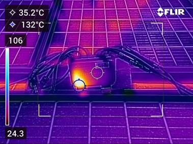
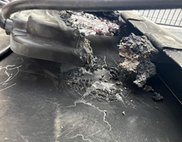
Early signs of RSD thermal failure include localized overheating and component deformation. If the component continues to operate after failure, localized damage to a module or peripheral area can occur. If it continues to overheat or melt, it can ignite combustible materials and result in a rooftop fire.
- Early Thermal Failure
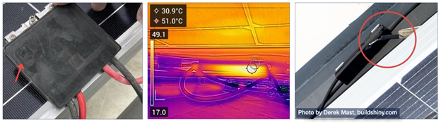
2. Full Component Thermal Damage (Localized, Contained)
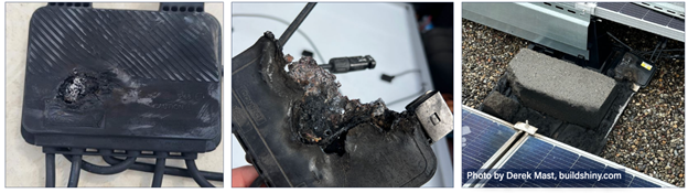
3. Full Component Thermal Damage Resulting in Rooftop Fire
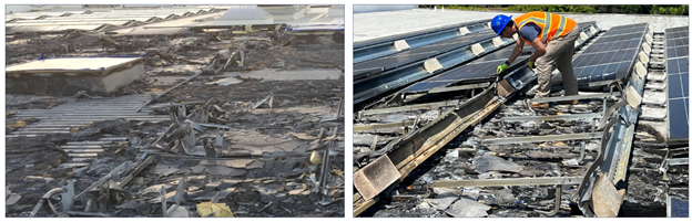
Rapid Shutdown and the NEC
How did we get here? Despite their risks, RSDs were developed and deployed with the best of intentions. Beginning in the early 2010s, firefighters and solar professionals began discussing PV-specific energy hazards and best practices for ensuring first responder safety as the growth of the US solar market accelerated.2
The specific rapid shutdown requirements in Section 690.1.2 of the NEC have evolved over time, with the 2023 revision requiring a drop to 80 V within 30 seconds for PV conductors within the array or adherence to UL 3741. Conductors outside one foot of the array boundary must reach 30 V in 30 seconds.
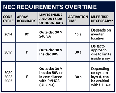
Our Public Input to the NEC
For its next revision, we recommend the NEC allow rapid shutdown compliance through a new, additional listing-based system approach rather than relying solely on rapid shutdown architectures and UL 3741 solutions. This evolution of the code is especially important because firefighter safety is affected not only by voltage-reduction strategy, but also by the long-term field reliability of the equipment architecture used to achieve that objective.
Our public input presented a concept for a system-level solution that addresses the real field conditions that materially affect firefighter safety and rooftop PV reliability. It ensures that firefighters do not encounter live wires when responding to emergencies by requiring robust installation and maintenance of the PV system, especially all electrical balance of systems, grounding, and bonding components.
In our view, this listing should be capable of evaluating the complete installation, including factors such as conductor routing, conductor separation, support, bend radius, equipment clearances, connector compatibility, and other installation-dependent conditions that can contribute to safety risks. The listing should also protect first responders from hazards due to degraded equipment and inadequate maintenance through periodic safety verifications during the project’s operational life.
Our proposal makes a complete, evaluated system approach the preferred compliance path, while retaining the existing rapid shutdown provisions as a fallback. This proposal does not seek to weaken firefighter protections. It seeks to preserve the life-safety objective of the NEC’s rapid shutdown requirement by allowing a listed-for-the-purpose system to serve as the primary means of shock-hazard reduction.
You can review this public input here. (Please note: users must create an NFPA account to access the public input submitted for the next edition of the NEC.)
MLPE: More Complexity, More Issues
RSDs also increase the likelihood of installation errors and intensify maintenance requirements in solar arrays. When RSDs (or any type of MLPE) are deployed, they not only add failure points to the array, but also increase rates of workmanship errors.
MLPE suppliers prescribe strict requirements for wire management, positioning, and attachment, as incorrect installation can result in failures or thermal events. Installers must deploy more supports for wiring, follow specific routing protocols, make more connections, and squeeze more components into a constrained space, and all without compromising airflow around the devices.
Given these challenges, it is not surprising that projects with MLPE have 34% higher rates of critical and major connector issues and 43% higher wire management and MLPE-specific issues, per HelioVolta’s inspection data. Both critical and major issues require urgent corrective action, but systems with critical issues must be de-energized (partial or total) and remediated ASAP, ideally before leaving the site.
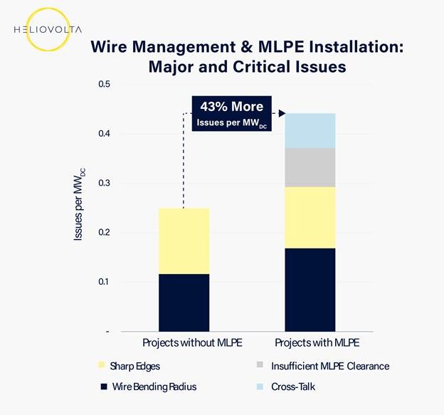
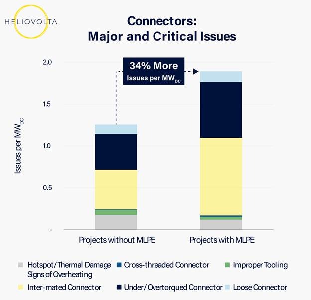
The following diagrams show a section of a string with four modules in various configurations. Without MLPE, there are five connector pairs. If one MLPE is used per two modules, the number of connector pairs jumps to 11. If the MLPE and module connectors do not match, 19 connector pairs are required to install just four modules and two MLPE.
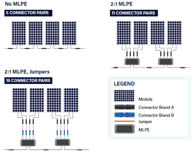
When MLPE are installed, there are more opportunities for hard-to-see defects to progress into failure events. These extra devices and connectors must be monitored and maintained as the system ages, but they are often installed in largely inaccessible locations.
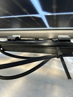
Common MLPE Installation Issues
We’ve addressed issues that HelioVolta sees most frequently in systems with RSDs and other types of MLPE below. Every MLPE has unique product and installation specifications that should be consulted in the field. Specific measurements are provided for contextual purposes only.
Cross-talk
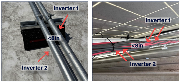
Most RSDs operate by processing a signal over the string conductor. This is called power line communication (PLC). The signal is unique to each individual inverter or transmitter. When conductors from different inverters are near each other (<8in typically), inductance between these conductors can introduce erroneous PLC signals to the RSDs that can lead to failure.
Insufficient Clearance
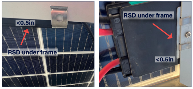
When an RSD (or other MLPE) is mounted too close to a PV module, the component does not have adequate airflow and cooling. The increase in heat adjacent to a PV module can lead to failure of the component and damage to the module. Required clearance is typically around 0.5in from the module backsheet, but specifications vary by manufacturer and should be confirmed in installation guides.
Wire Bending Radius
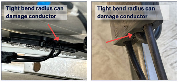
Not complying with manufacturer-specified wire bending radius requirements puts strain on the strands inside the conductor and mechanical components. Wire bending radius issues are common in RSD projects because wire management is complex.
Improper Wire Routing
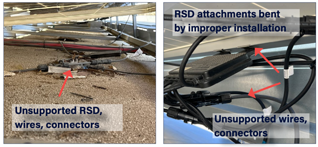
MLPE increase wire management complexity, so issues are more likely to occur. Conductors routed over sharp edges are susceptible to insulation damage from pulling wires and thermal cycling. Lack of wire management supports can expose components to moisture, water, and UV light, accelerating degradation.
MLPE: More Complexity, More Issues
Projects with MLPE have 34% higher rates of critical and major connector issues and 43% higher wire management and MLPE-specific issues, per HelioVolta’s inspection data. Both critical and major issues require urgent corrective action, but systems with critical issues must be de-energized (partial or total) and remediated ASAP, ideally before leaving the site.
At a basic level, MLPE increase connector issues because they increase the quantity of PV connectors by a factor of two to three. This creates more failure points in the system. MLPE also add wiring to PV systems, and complicated wire management increases the risk of improper installation. MLPE suppliers prescribe strict requirements for wire management, positioning, and attachment, as incorrect installation can result in failures or thermal events.
How to Mitigate RSD Risk
Commercial solar PV system designers, installers, owners, and hosts can take action to reduce the risk of RSD safety issues in their portfolios. During system design and recruitment, we recommend that you:
- Avoid use of RSDs and consider UL 3741-compliant designs.
- Include a manufacturer-compliant wire management approach in plans.
- Specify requirements for proper mounting, wire bending radius, and string routing to avoid cross-talk in design packages.
- Ensure MLPEs, PV modules, and inverters use the same factory-made connectors. Verify shipments upon delivery.
- Review and approve any orders for field-made connector kits.
Once you enter the construction phase, EPC training and quality control and assurance are also necessary. It is important to inspect 100% of MLPEs, associated components, and field-made connectors for compliance with design requirements, drawings, and manufacturer specifications.
Systems with RSDs: Operations and Maintenance
Those who own, operate, or host a system with RSDs are faced with a small set of less-than-ideal options to reduce failure risks. Asset owners cannot accurately model the relative risk of replacing RSDs with other components or pursuing UL 3741 solutions because industry- wide failure root cause data for RSDs (and PV system fires more broadly) is not available in the US.
In practical terms, most rooftop asset owners choose to continue operating PV systems with RSDs. These O&M tactics can reduce operational risks in portfolios with RSDs:
- Leverage data acquisition systems (DAS) to remotely monitor for signs of RSD failure, such as voltage imbalances (VOC and VMPP).
- Where possible, configure remote DAS to send RSD-specific alerts. Ensure alarms are acknowledged and acted upon.
- Never leave a failed RSD connected to the string.
- Include visual and thermal RSD inspections and safety voltage checks in preventive maintenance scopes at minimum once a year, ideally before summer.
- Inspect and clean rooftops regularly. Keep debris and combustible materials away from RSDs.
CONCLUSION
Solar adopters, project owners, building owners and tenants, not component manufacturers, ultimately bear the most painful consequences of RSD failures. We believe US businesses and consumers deserve rooftop PV systems that provide safe, reliable, and cost-effective clean power.
In our experience, the increased risks posed by RSDs have led to more fires on PV systems, outweighing the potential benefits of the rapid shutdown systems required by code. Regulations should evolve to lessen reliance on RSDs in pursuit of more reliable alternatives that achieve the NEC safety objective.
PV professionals must work with first responders to ensure the safe operation of rooftop solar power plants. We greatly appreciate the first responders and our industry peers who have contacted HelioVolta in recent weeks to discuss PV system safety.
We look forward to continuing this conversation. If you’re interested in discussing rapid shutdown, please reach out to our team. We hope to hear from you soon.
FAQ's
What is a rapid shutdown system and how does it work?
Answer: Rapid shutdown is a PV safety function that reduces the voltage on PV conductors when an initiation device signals it is necessary, most commonly when the inverter disconnects from AC, is turned off, or trips on a fault. In typical systems, the inverter or a dedicated transmitter sends a “keep-alive” signal over the DC conductors via power line communication (PLC). If that signal is lost, rapid shutdown is initiated and the RSDs reduce module voltage. Under the 2023 NEC, conductors within the array must reduce to 80 V within 30 seconds (or comply via UL 3741), and conductors more than one foot outside the array boundary must reduce to 30 V within 30 seconds.
What is a Rapid Shutdown Device (RSD), and how is it different from other MLPE?
Answer: An RSD is a module-level power electronic device whose sole function is rapid shutdown for NEC compliance; it does not provide performance or reliability benefits. RSDs depend on a PLC “keep-alive” signal from their paired transmitter; loss of that signal triggers shutdown. By contrast, other MLPE like power optimizers and microinverters also manage module-level power (mitigating shading and mismatch), and power optimizers commonly provide more sophisticated communications with the inverter. Microinverters are mainly used in residential systems and are not part of HelioVolta’s data set.
Why are RSDs prone to failure and considered a safety risk?
Answer: Our report cites four main reasons: (1) Validation gaps: UL 1741 PVRSE/PVRSS focuses on lab testing and inverter-centric criteria, not full-system, real-world RSD behavior; (2) Installation complexity: frequently changing, product-specific requirements increase workmanship errors; (3) Fragile communications: PLC can suffer cross-talk when conductors from different inverters are too close, causing RSDs to “chatter” (rapidly open/close) and fail; and (4) Scale: deploying many long-life electronics on rooftops can turn even small defect rates into widespread field risk. Added complexity from extra connectors, jumpers for connector mismatch, tight clearances, small wire-bend radii, and challenging wire routing further increases the likelihood of thermal events and long-term reliability issues.
What evidence shows the scale of RSD-related risks?
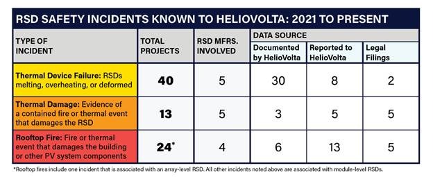
Answer: From inspections of 500+ commercial rooftop systems and industry research, we report that at least 77 high-risk safety incidents tied to RSDs since 2021, including 23 fires. PV systems with RSDs are 66% more likely to have critical safety risks than systems without MLPE, and systems with MLPE show 34% higher rates of critical/major connector issues and 43% higher rates of wire-management and MLPE-specific issues.
HelioVolta has observed RSD failures progressing from localized overheating and deformation to full component damage and, in some cases, rooftop fires. Despite rapid shutdown’s original intent, public data is limited and often confidential, leaving the true scope of RSD failures and safety risks underreported.
How can teams mitigate RSD-related risks or comply without them?
Answer: For new designs, avoid RSDs where feasible and consider UL 3741-compliant PV hazard control systems. If MLPE/RSDs are used, design for manufacturer-compliant wire management, specify proper mounting clearances and wire-bend radii, and plan string routing to minimize PLC cross-talk (maintain required conductor separation and follow any signal-conditioning guidance).
Ensure MLPE, modules, and inverters use matching factory-made connectors; review any field-made connector kits; and inspect 100% of MLPE and connectors for compliance during installation. For O&M, monitor DAS for RSD failure indicators (e.g., VOC/VMPP imbalances), configure RSD-specific alerts and act on them, never leave a failed RSD in-circuit, perform annual visual/thermal inspections and safety-voltage checks (ideally before summer), and keep rooftops clear of debris and combustibles around RSDs.
REFERENCES
1 Weaver, John Fitzgerald. 2019. “There Are –data Missing– Solar Power Fires per Year.” PV Magazine USA. August 22, 2019. https://pv-magazine- usa.com/2019/08/22/there-are-solar-power-fires-per-year/
2 Greene, Chris, and Tony Granato. 2025. “Rapid Shutdown: The Photovoltaic Safety Feature You’ve Never Heard Of.” Fire Engineering, February 1, 2025. https://www.fireengineering.com/magazine/rapid-shutdown-the-photovoltaic-safety-feature-youve-never-heard-of/